 |
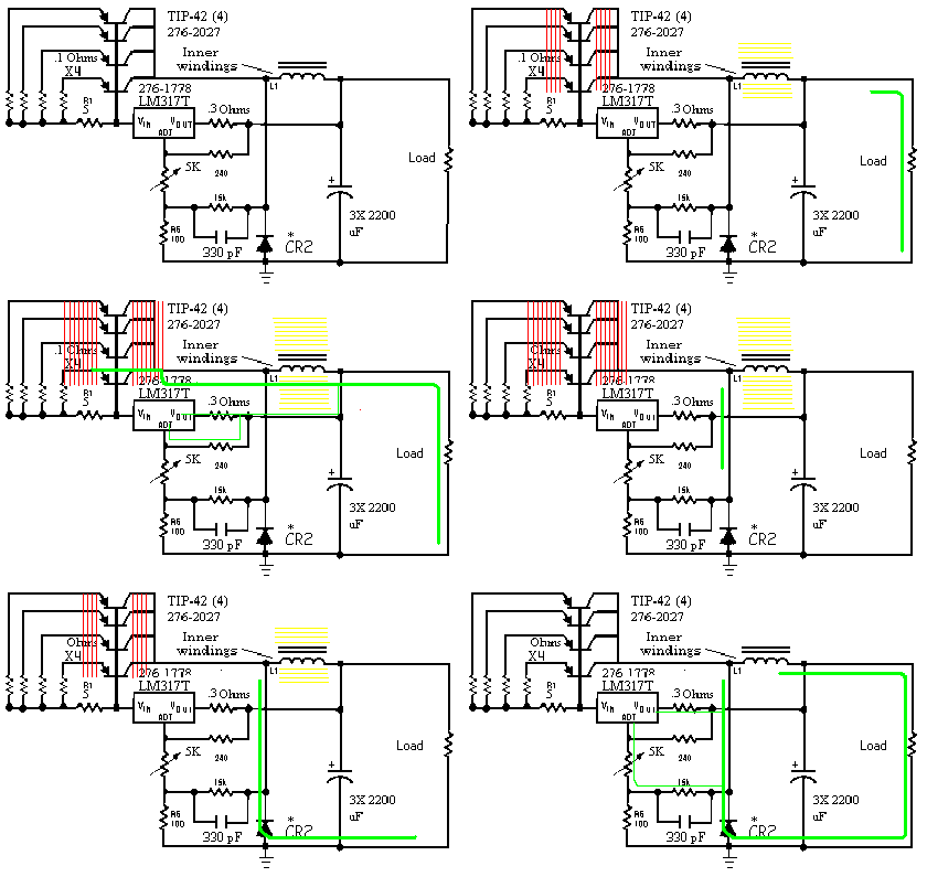
| At the Heart of the 5 and 3.3 Volt circuitry is a LM317 adjustable linear regulator. The regulator is configured as a switch mode controller with the addition of a large power inductor, and switch transistors. The additional current requirements demand that additional pass transistors be parralleled using .1 Ohm resistors to balance out the circuit. When the regulator switches the transistors on, they heat up, when the regulator switches them off, they cool down. At initial turn on, the output of the regulator is less than the reference at the adjust terminal, and the regulator turns on. This pulls current though the 5 Ohm resistor connected to the input. This pulls the Base of the pass transistors slightly negative and causes them to turn on. Current flows through the load, and through L1 and a magnetic field begins to build up in L1's core. As the output of the regulator approaches the reference voltage applied to the adjust terminal, the regulator starts to turn off. This in turn causes the pass transistors to turn off. The magnetic field built up in the inductor core begins to collaps inducing a voltage into the windings. This voltage is equal and opposite of the charging current. This voltage causes current to flow through CR2 and the load back to the opposite end of the coil. A small amount of the Inductive kick is fed into the adjust terminal via the 15 KOhm resistor to ensure it stays in the off state while the inductor discharges. The 300 pF capacitor causes a phase change that prevents the regulator output from catching up the the adjust terminal, and keeps the oscillations going. Although this is a switch mode supply, it's efficiency suffers a bit from having a linear controller. The Power transistors are never fully on or off, and operate in more of a linear fashion than a true switch mode controller. I estamate the efficiency for the +3.3 and 5 Volts circuits at 75%. |