 |
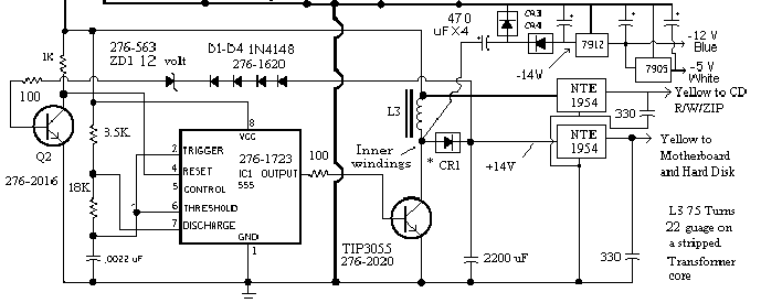
| The 12 Volt circuit is Boost regulator with a linear follower. At the Heart of the +/- 12 and -5 Volt circuitry is a LM555 Timer configured as an Astable Multivibrator. The output of the 555 is passed into the 12 Volt switch transistor via a 100 ohm resistor. The transistor turns on and effectivly shorts the 12 Volts through the power inductor. This causes a magnetic field to build up in the core. When the output of the 555 toggles to the off state, the magnetic field in the power inductor collapses, causing a voltage to be induced into the inductor windings. This voltage is opposite in polarity from the charging Voltage, and adds to the charging voltage. When the voltage at the input of the linear follower reaches + 14 Volts, the feedback circuit composed of a 12 Volt Zener and 4 regular diodes turns on and shuts off the 555. The 14 volts is rectified by CR3, and filtered by a 2200 uF capacitor and fed into a low dropout linear regulator. A 470 uF connected to the inner windings of L1 couples 14 Volts AC into a half wave negative rectifier. The resulting -14 volts is fed into -12 and -5 volt regulators. The boost section of the circuit is a true switch mode supply, and is quite effecient. The overall efficiency suffers due to the Linear follower. Without the linear regulator, the 12 Volt supply would be connected directly to the output via L3 and CR1. The overall efficiency of the circuit is estimated at 85%. |